| balbes | Дата: Среда, 06.03.2013, 03:34 | Сообщение # 1 |
 3.5 Вольт
Группа: Пользователи
Сообщений: 10
Репутация: 0
Статус: Offline
| 
подскажите пожалуйста как подключить к этому шылду 4 движка и примеры скетча хотя бы на 2движка
Добавлено (06.03.2013, 03:34)
---------------------------------------------
мой первый опыт
удалось покрутить четырьмя моторами по очереди в разных направлениях через Serial port
скетч ниже
Код /*
Shift Register Example
for 74HC595 shift register
Created 22 May 2009
Created 23 Mar 2010
by Tom Igoe
*/
//Пин подключен к ST_CP входу 74HC595
int latchPin = 12;
//Пин подключен к SH_CP входу 74HC595
int clockPin = 4;
//Пин подключен к DS входу 74HC595
int dataPin = 8;
int cloPin = 7;
void setup() {
//устанавливаем режим OUTPUT
pinMode(latchPin, OUTPUT);
pinMode(dataPin, OUTPUT);
pinMode(clockPin, OUTPUT);
pinMode(cloPin, OUTPUT);
Serial.begin(9600);
Serial.println("reset");
}
void loop() {
if (Serial.available() > 0) {
// Символы от '0' до '9'
// представлены в ASCII таблице значения от 48 до 57.
int bitToSet = Serial.read() - 48;
// Записываем HIGH в позицию соответствующую bitToSet
registerWrite(bitToSet, HIGH);
}
}
// Этот метот записывает байт в регистр
void registerWrite(int whichPin, int whichState) {
// инициализируем и обнуляем байт
byte bitsToSend = 0;
//Отключаем вывод на регистре
digitalWrite(latchPin, LOW);
// устанавливаем HIGH в соответствующем бите
bitWrite(bitsToSend, whichPin, whichState);
// проталкиваем байт в регистр
shiftOut(dataPin, clockPin, MSBFIRST, bitsToSend);
вал
Сообщение отредактировал balbes - Вторник, 05.03.2013, 16:22 |
| |
| |
| balbes | Дата: Суббота, 16.03.2013, 02:41 | Сообщение # 3 |
|
3.5 Вольт
Группа: Пользователи
Сообщений: 10
Репутация: 0
Статус: Offline
| обновленные библиотеки установил . в среду ардуино 1.0.3 но примеры не компилируются выдают ошибки библиотеки
среды ниже 1.0 использовать не магу потому что у меня ардуино Леонардо
нашел еще один скетч управляет сервами и движками плюс нагрузкой
а пробовал работает но надо добавить в него шим.
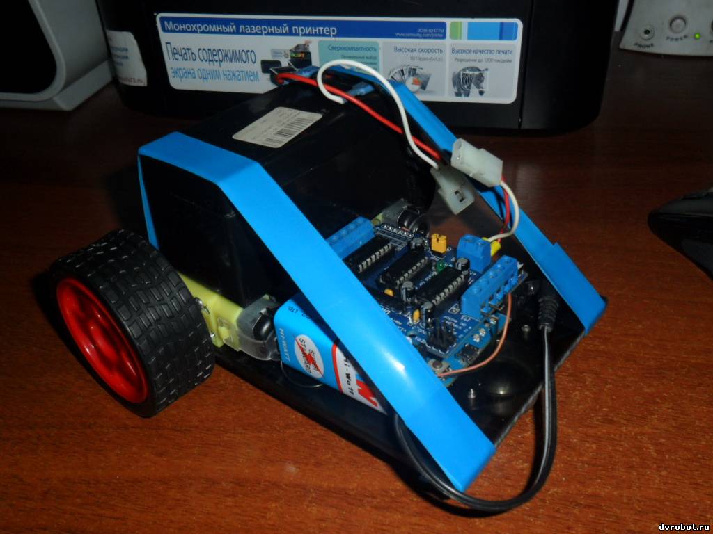
вот мая первая сборка под управлением этого скетча

кодКод // Simple Adafruit Motor Shield sketch
// -----------------------------------
//
// By arduino.cc user "Krodal".
// June 2012
// Open Source / Public Domain
//
// Using Arduino 1.0.1
//
// A simple sketch for the Adafruit motor shield,
// without using the Adafruit library.
//
// The outputs can be used for DC-motors
// (either full H-bridge or just On and Off), lights,
// relays, solenoids, etc.
// But stepper motors can not be used !
// Servo motors can be used with the default Servo library.
//
// A maximum of 4 DC motors can be used with full-bridge,
// or a maximum of 8 normal outputs, or a combination.
// Two servo motors can always be used, they use the +5V
// of the Arduino board, so the voltage regulator could
// get hot.
//
// Tested with an Ebay clone with the Arduino Uno.
//
// Parts of the code are from the Adafruit Motor Shield
// library.
// The Adafruit program is public domain.
// This code is also public domain
//
// This simplified program is using the normal
// Arduino library functions as much as possible.
//
// The motors will make a whistling sound,
// due to the analogWrite() PWM frequency.
// The Adafruit library is specifically designed to avoid
// this, so use the Adafruit library for a better result.
//
//
//
// Connector usage
// ---------------
// The order is different than what you would expect.
// If the Arduino (Uno) board is held with the USB
// connector to the left, the positive (A) side is
// at the top (north), and the negative (B) side is
// the bottom (south) for both headers.
//
// Connector X1:
// M1 on outside = MOTOR1_A (+) north
// M1 on inside = MOTOR1_B (-)
// middle = GND
// M2 on inside = MOTOR2_A (+)
// M2 on outside = MOTOR2_B (-) south
//
// Connector X2:
// M3 on outside = MOTOR3_B (-) south
// M3 on inside = MOTOR3_A (+)
// middle = GND
// M4 on inside = MOTOR4_B (-)
// M4 on outside = MOTOR4_A (+) north
//
//
// -------------------------------
// | -+s |
// | -+s |
// M1 A | | M4 A
// M1 B | | M4 B
// GND | | GND
// M2 A | | M3 A
// M2 B | | M3 B
// | ..... |
// -------------------------------
// + -
//
//
//
// Pin usage with the Adafruit Motorshield
// ---------------------------------------
// Analog pins: not used at all
// A0 ... A5 are still available
// They all can also be used as digital pins.
// Also I2C (A4=SDA and A5=SCL) can be used.
// These pins have a breadboard area on the shield.
// Digital pins: used: 3,4,5,6,7,8,9,10,11,12
// Pin 9 and 10 are only used for the servo motors.
// Already in use: 0 (RX) and 1 (TX).
// Unused: 2,13
// Pin 2 has an soldering hole on the board,
// easy to connect a wire.
// Pin 13 is also connected to the system led.
// I2C is possible, but SPI is not possible since
// those pins are used.
//
#include <Servo.h>
// Arduino pins for the shift register
#define MOTORLATCH 12
#define MOTORCLK 4
#define MOTORENABLE 7
#define MOTORDATA 8
// 8-bit bus after the 74HC595 shift register
// (not Arduino pins)
// These are used to set the direction of the bridge driver.
#define MOTOR1_A 2
#define MOTOR1_B 3
#define MOTOR2_A 1
#define MOTOR2_B 4
#define MOTOR3_A 5
#define MOTOR3_B 7
#define MOTOR4_A 0
#define MOTOR4_B 6
// Arduino pins for the PWM signals.
#define MOTOR1_PWM 11
#define MOTOR2_PWM 3
#define MOTOR3_PWM 6
#define MOTOR4_PWM 5
#define SERVO1_PWM 10
#define SERVO2_PWM 9
// Codes for the motor function.
#define FORWARD 1
#define BACKWARD 2
#define BRAKE 3
#define RELEASE 4
// Declare classes for Servo connectors of the MotorShield.
Servo servo_1;
Servo servo_2;
void setup()
{
Serial.begin(9600);
Serial.println("Simple Adafruit Motor Shield sketch");
// Use the default "Servo" library of Arduino.
// Attach the pin number to the servo library.
// This might also set the servo in the middle position.
servo_1.attach(SERVO1_PWM);
servo_2.attach(SERVO2_PWM);
}
void loop()
{
// Suppose there are two servo motors connected.
// Let them move 180 degrees.
servo_1.write(0);
delay(1000);
servo_1.write(180);
delay(2000);
servo_2.write(0);
delay(1000);
servo_2.write(180);
delay(2000);
// Suppose there is a relay, or light or solenoid
// connected to M3_A and GND.
// Note that the 'speed' (the PWM, the intensity)
// is for both M3_A and M3_B.
// The output is a push-pull output (half bridge),
// so it can also be used to drive something low.
// The 'speed' (the PWM, the intensity) can be set
// to zero, that would make the output disabled
// and floating.
motor_output(MOTOR3_A, HIGH, 255);
delay(2000);
motor_output(MOTOR3_A, LOW, 255);
// Suppose a DC motor is connected to M1_A(+) and M1_B(-)
// Let it run full speed forward and half speed backward.
// If 'BRAKE' or 'RELEASE' is used, the 'speed' parameter
// is ignored.
motor(4, FORWARD, 160);
motor(1, FORWARD, 160);
delay(3000);
// Be friendly to the motor: stop it before reverse.
motor(4, RELEASE, 0);
motor(1, RELEASE, 0);
delay(1000);
motor(4, BACKWARD, 160);
motor(1, BACKWARD, 160);
delay(2000);
motor(4, RELEASE, 0);
motor(1, RELEASE, 0);
delay(1000);
}
// Initializing
// ------------
// There is no initialization function.
//
// The shiftWrite() has an automatic initializing.
// The PWM outputs are floating during startup,
// that's okay for the Adafruit Motor Shield, it stays off.
// Using analogWrite() without pinMode() is valid.
//
// ---------------------------------
// motor
//
// Select the motor (1-4), the command,
// and the speed (0-255).
// The commands are: FORWARD, BACKWARD, BRAKE, RELEASE.
//
void motor(int nMotor, int command, int speed)
{
int motorA, motorB;
if (nMotor >= 1 && nMotor <= 4)
{
switch (nMotor)
{
case 1:
motorA = MOTOR1_A;
motorB = MOTOR1_B;
break;
case 2:
motorA = MOTOR2_A;
motorB = MOTOR2_B;
break;
case 3:
motorA = MOTOR3_A;
motorB = MOTOR3_B;
break;
case 4:
motorA = MOTOR4_A;
motorB = MOTOR4_B;
break;
default:
break;
}
switch (command)
{
case FORWARD:
motor_output (motorA, HIGH, speed);
motor_output (motorB, LOW, -1); // -1: no PWM set
break;
case BACKWARD:
motor_output (motorA, LOW, speed);
motor_output (motorB, HIGH, -1); // -1: no PWM set
break;
case BRAKE:
// The AdaFruit library didn't implement a brake.
// The L293D motor driver ic doesn't have a good
// brake anyway.
// It uses transistors inside, and not mosfets.
// Some use a software break, by using a short
// reverse voltage.
// This brake will try to brake, by enabling
// the output and by pulling both outputs to ground.
// But it isn't a good break.
motor_output (motorA, LOW, 255); // 255: fully on.
motor_output (motorB, LOW, -1); // -1: no PWM set
break;
case RELEASE:
motor_output (motorA, LOW, 0); // 0: output floating.
motor_output (motorB, LOW, -1); // -1: no PWM set
break;
default:
break;
}
}
}
// ---------------------------------
// motor_output
//
// The function motor_ouput uses the motor driver to
// drive normal outputs like lights, relays, solenoids,
// DC motors (but not in reverse).
//
// It is also used as an internal helper function
// for the motor() function.
//
// The high_low variable should be set 'HIGH'
// to drive lights, etc.
// It can be set 'LOW', to switch it off,
// but also a 'speed' of 0 will switch it off.
//
// The 'speed' sets the PWM for 0...255, and is for
// both pins of the motor output.
// For example, if motor 3 side 'A' is used to for a
// dimmed light at 50% (speed is 128), also the
// motor 3 side 'B' output will be dimmed for 50%.
// Set to 0 for completelty off (high impedance).
// Set to 255 for fully on.
// Special settings for the PWM speed:
// Set to -1 for not setting the PWM at all.
//
void motor_output (int output, int high_low, int speed)
{
int motorPWM;
switch (output)
{
case MOTOR1_A:
case MOTOR1_B:
motorPWM = MOTOR1_PWM;
break;
case MOTOR2_A:
case MOTOR2_B:
motorPWM = MOTOR2_PWM;
break;
case MOTOR3_A:
case MOTOR3_B:
motorPWM = MOTOR3_PWM;
break;
case MOTOR4_A:
case MOTOR4_B:
motorPWM = MOTOR4_PWM;
break;
default:
// Use speed as error flag, -3333 = invalid output.
speed = -3333;
break;
}
if (speed != -3333)
{
// Set the direction with the shift register
// on the MotorShield, even if the speed = -1.
// In that case the direction will be set, but
// not the PWM.
shiftWrite(output, high_low);
// set PWM only if it is valid
if (speed >= 0 && speed <= 255)
{
analogWrite(motorPWM, speed);
}
}
}
// ---------------------------------
// shiftWrite
//
// The parameters are just like digitalWrite().
//
// The output is the pin 0...7 (the pin behind
// the shift register).
// The second parameter is HIGH or LOW.
//
// There is no initialization function.
// Initialization is automatically done at the first
// time it is used.
//
void shiftWrite(int output, int high_low)
{
static int latch_copy;
static int shift_register_initialized = false;
// Do the initialization on the fly,
// at the first time it is used.
if (!shift_register_initialized)
{
// Set pins for shift register to output
pinMode(MOTORLATCH, OUTPUT);
pinMode(MOTORENABLE, OUTPUT);
pinMode(MOTORDATA, OUTPUT);
pinMode(MOTORCLK, OUTPUT);
// Set pins for shift register to default value (low);
digitalWrite(MOTORDATA, LOW);
digitalWrite(MOTORLATCH, LOW);
digitalWrite(MOTORCLK, LOW);
// Enable the shift register, set Enable pin Low.
digitalWrite(MOTORENABLE, LOW);
// start with all outputs (of the shift register) low
latch_copy = 0;
shift_register_initialized = true;
}
// The defines HIGH and LOW are 1 and 0.
// So this is valid.
bitWrite(latch_copy, output, high_low);
// Use the default Arduino 'shiftOut()' function to
// shift the bits with the MOTORCLK as clock pulse.
// The 74HC595 shiftregister wants the MSB first.
// After that, generate a latch pulse with MOTORLATCH.
shiftOut(MOTORDATA, MOTORCLK, MSBFIRST, latch_copy);
delayMicroseconds(5); // For safety, not really needed.
digitalWrite(MOTORLATCH, HIGH);
delayMicroseconds(5); // For safety, not really needed.
digitalWrite(MOTORLATCH, LOW);
}
вал
Сообщение отредактировал balbes - Воскресенье, 24.03.2013, 19:55 |
| |
| |